Rethinking vehicle connectivity: The engineering behind the integrated Connectivity Hub Module (CHM)
2026-05-27
By: Aaron Leiba, Executive Director, Compute and Connectivity Hardware
As vehicle engineering and digital systems converge, the vehicle itself is being reimagined and software-defined at its foundation – not with software layered on afterward. At the center of this shift is connectivity, enabling secure updates, diagnostics, telemetry, and more personalized experiences while providing the visibility and control needed to validate, maintain, and continuously improve quality- and safety-critical functions.
Supporting communication across cellular, Wi-Fi, Bluetooth (BT), Bluetooth Low Energy (BLE), Ultra-Wideband (UWB), and high-precision Global Navigation Satellite System (GNSS) – alongside the compute and sensor-fusion demands of advanced driver assistance and autonomy – requires a robust, high-bandwidth architecture. For years, the industry met that need with a familiar compromise: more exterior antennas and long runs of heavy, costly coaxial cable routed to a centralized Telematics Control Unit (TCU) buried deep within the cabin.
Today, the demands of massive data ingestion, split-second autonomous decision-making, and over-the-air (OTA) capabilities have pushed legacy architecture to its physical and economic limits.
GM’s modernized approach to vehicle connectivity
To support GM’s next-generation software-defined vehicle architecture – where connectivity must seamlessly deliver OTA updates, high-bandwidth infotainment, and data-rich services – we are converging on a radically different approach: the integrated Connectivity Hub Module (CHM). As a unified connectivity node, the CHM places all major radios at the optimal radio-frequency (RF) location and presents a clean, high-bandwidth digital interface into the electrical architecture’s core compute and broader vehicle network.
By integrating antennas directly with the connectivity electronics and placing the module at the optimal RF location – such as the roof – we are rethinking the hardware foundation of the software-defined vehicle. This architectural choice dramatically improves cost, mass, volume, and RF performance, but it also introduces complex multi-physics engineering challenges, most notably receiver desensitization, RF coexistence, and thermal load.
How integrated CHM solves the traditional connectivity dilemma
In a classical connectivity stack, the system is explicitly divided: a roof-mounted "shark fin" houses the passive or active antennas, while a TCU sits elsewhere in the vehicle, connected by up to five meters of dedicated coaxial cables.
While a modular approach places antennas in an ideal location, it brings severe physical and logistical bottlenecks. High-frequency signals, especially the gigahertz bands used in 5G Cellular and Wi-Fi, experience significant insertion loss as they travel through long cables and impedance mismatches at connectors. This results in degraded performance and a significant part number count to manage at an enterprise level. Additionally, thick bundles of coaxial cables consume valuable packaging volume, add mass, complicate electromagnetic compatibility (EMC), and require expensive connectors that complicate assembly plant operations.
The integrated CHM collapses this distributed architecture into a single, highly optimized edge node. By combining the network processors, memory, RF transceivers, antenna arrays, and a dedicated backup battery for OnStar functionality into a unified module, the CHM acts as a complete, self-contained connectivity hub.
This consolidation provides immense engineering benefits, but realizing these advantages requires navigating the uncompromising laws of electromagnetics and thermodynamics.
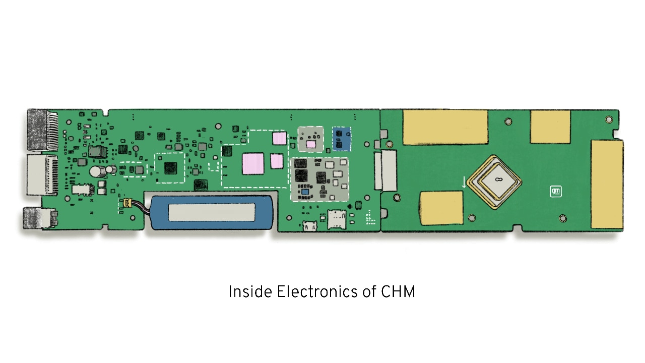
Image Caption: Diagram of the integrated CHM showing antennas and electronics parts for assembly.
Technical merits of antenna-TCU integration
At GM, we have found that antenna integration provides an efficient approach to connectivity with advantages that stretch across performance, design, and overall system cost.
Eliminates cable loss and boosting performance
In RF engineering, every decibel (dB) of signal matters. A standard automotive coaxial run (transmission line) can degrade high-frequency signals by several decibels before even reaching the receiver. Integrating the antennas directly onto the CHM’s printed circuit board (PCB) and inside the same housing eliminates the cable run. This maximizes Signal-to-Noise Ratio (SNR) and drastically improves the link budget, resulting in faster data throughput, greater range for high-bandwidth applications, and highly reliable connection even in fringe coverage areas where our customers adventure.
Addresses the desense challenge
While integration minimizes transmission line loss, it introduces one of the most notoriously difficult challenges in mixed-signal engineering: desense (receiver desensitization).
An integrated CHM is essentially a high-performance computer packed with ultra-fast gigabit Ethernet switches, Double Data Rate (DDR) memory interfaces, Peripheral Component Interconnect Express (PCIe) buses, and high-current power supplies all radiating broadband electromagnetic noise. When highly sensitive receiver antennas are integrated right next to this roaring digital engine, the noise floor is artificially raised, effectively "blinding" or de-sensitizing the antennas to faint incoming signals from cell towers or satellites.
Board-level desense control is a critical enabler for the CHM and demands aggressive Electromagnetic Compatibility (EMC) strategies. Engineers use intricate multi-cavity RF shields to isolate the digital System on Chip (SoC) from the RF front-end, along with advanced PCB stack-ups featuring dedicated ground planes and buried stripline routing to contain return currents. They also tune drive strength and spread-spectrum clocks and design localized filtering topologies that suppress harmonic noise at the source. Success depends on extreme physical packaging and lock-step coordination across electrical, software, mechanical, and RF engineering.
Resolves the radio coexistence (Coex) puzzle
If desense is the threat of internal digital noise, coexistence (coex) is the challenge of the radios shouting over one another. The CHM packs cellular, Wi-Fi, BT, BLE, UWB, and GNSS into a highly constrained volume. These distinct radios frequently operate in adjacent or overlapping frequency bands. A high-power Wi-Fi transmission, for example, can easily spill into adjacent cellular bands or completely deafen the highly sensitive GNSS receiver.
Solving the coex puzzle requires a rigorous, multi-layered approach. At the physical level, RF engineers must achieve every decibel of antenna isolation within a tiny footprint, leveraging spatial diversity and orthogonal polarization. Electrically, the board architecture relies on high-performance acoustic wave filters to create incredibly sharp cutoffs between active bands. Finally, at the software layer, the CHM utilizes advanced time-domain multiplexing to intelligently coordinate transmission schedules, ensuring the radios interleave their signals without stepping on each other.
Powers the thermal management equation
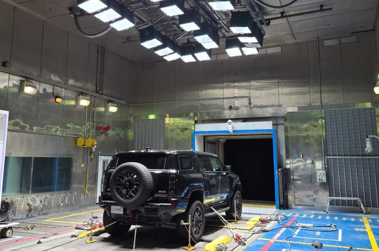
Image Caption: Solar load testing simulates the direct heating effect on CHM when a vehicle sits in the sun.
Bringing the computing power of a TCU to the roof of the vehicle introduces a profound thermal challenge. The vehicle's roof is subject to immense solar loading, often reaching extreme temperatures in the summer sun. Simultaneously, the 5G transceivers and network processors inside the CHM generate substantial internal heat.
Because the CHM must be heavily sealed against water and dust ingress, engineers cannot rely on active fan cooling. Instead, thermal management must be achieved through innovative mechanical design.
This approach uses the module’s cast aluminum housing as a structural heat sink and advanced thermal interface materials (TIMs) to move heat away from critical components. It also relies on intelligent software to dynamically throttle compute or transmission power during peak thermal events while preserving safety-critical communications.
Beyond RF and digital components, housing a battery in a roof-mounted module exacerbates the thermal and packaging challenges, requiring sophisticated charge management algorithms to ensure reliability and safety across extreme temperature cycles.
Supports drastic reductions in mass and volume – and improved reliability
Automotive-grade RF cables are stiff, heavy, and difficult to route during manufacturing. In addition to mass and volume, every interconnect is a potential failure point of the system and historically has led to quality challenges. By entirely stripping meters of multi-core coaxial cabling out of the vehicle architecture, the CHM immediately yields mass reductions as well as reliability improvements. With electric vehicles, every gram saved contributes directly to range optimization and overall vehicle efficiency. This integration frees up critical volumetric space within the vehicle’s pillars, headliner, and instrument panel – reducing the complexity of the overarching wiring harness designs greater freedom.
Optimizes system cost and manufacturing
Coaxial cables and their associated automotive-grade connectors are some of the most expensive passive components in a vehicle’s electrical architecture. They require rigorous validation to ensure they do not degrade over years of thermal cycling and vibration. By consolidating the antennas and electronics, we slash the Bill of Materials (BOM). Additionally, installing a single CHM on the assembly line via a standard digital connection (like Automotive Ethernet) is vastly more efficient than routing long RF cables and mating multiple fragile connectors, driving down labor costs, and reducing potential manufacturing defects.
Conclusion
The integrated CHM is a necessary step for the future of intelligent vehicles. It trades the straightforward, but inefficient, legacy cable architectures for a highly optimized, physically demanding integrated design.
By balancing the aggressive performance demands of modern networks with the exacting physics of desense mitigation, thermal management, and power resilience, the integrated CHM delivers a connectivity foundation that is lighter, more cost-effective, and vastly more capable. This kind of foundational engineering within GM is shaping next-generation connected vehicles and redefining what it means to keep millions of people safe, informed, and connected on the move.
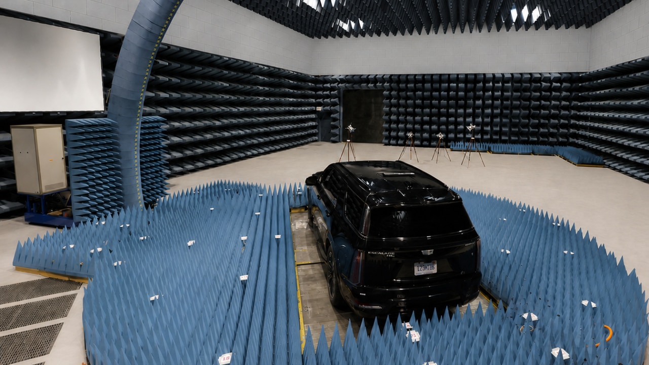
GM’s EMC testing lab at Milford Proving Ground in Michigan.
By: Aaron Leiba, Executive Director, Compute and Connectivity Hardware
As vehicle engineering and digital systems converge, the vehicle itself is being reimagined and software-defined at its foundation – not with software layered on afterward. At the center of this shift is connectivity, enabling secure updates, diagnostics, telemetry, and more personalized experiences while providing the visibility and control needed to validate, maintain, and continuously improve quality- and safety-critical functions.
Supporting communication across cellular, Wi-Fi, Bluetooth (BT), Bluetooth Low Energy (BLE), Ultra-Wideband (UWB), and high-precision Global Navigation Satellite System (GNSS) – alongside the compute and sensor-fusion demands of advanced driver assistance and autonomy – requires a robust, high-bandwidth architecture. For years, the industry met that need with a familiar compromise: more exterior antennas and long runs of heavy, costly coaxial cable routed to a centralized Telematics Control Unit (TCU) buried deep within the cabin.
Today, the demands of massive data ingestion, split-second autonomous decision-making, and over-the-air (OTA) capabilities have pushed legacy architecture to its physical and economic limits.
GM’s modernized approach to vehicle connectivity
To support GM’s next-generation software-defined vehicle architecture – where connectivity must seamlessly deliver OTA updates, high-bandwidth infotainment, and data-rich services – we are converging on a radically different approach: the integrated Connectivity Hub Module (CHM). As a unified connectivity node, the CHM places all major radios at the optimal radio-frequency (RF) location and presents a clean, high-bandwidth digital interface into the electrical architecture’s core compute and broader vehicle network.
By integrating antennas directly with the connectivity electronics and placing the module at the optimal RF location – such as the roof – we are rethinking the hardware foundation of the software-defined vehicle. This architectural choice dramatically improves cost, mass, volume, and RF performance, but it also introduces complex multi-physics engineering challenges, most notably receiver desensitization, RF coexistence, and thermal load.
How integrated CHM solves the traditional connectivity dilemma
In a classical connectivity stack, the system is explicitly divided: a roof-mounted "shark fin" houses the passive or active antennas, while a TCU sits elsewhere in the vehicle, connected by up to five meters of dedicated coaxial cables.
While a modular approach places antennas in an ideal location, it brings severe physical and logistical bottlenecks. High-frequency signals, especially the gigahertz bands used in 5G Cellular and Wi-Fi, experience significant insertion loss as they travel through long cables and impedance mismatches at connectors. This results in degraded performance and a significant part number count to manage at an enterprise level. Additionally, thick bundles of coaxial cables consume valuable packaging volume, add mass, complicate electromagnetic compatibility (EMC), and require expensive connectors that complicate assembly plant operations.
The integrated CHM collapses this distributed architecture into a single, highly optimized edge node. By combining the network processors, memory, RF transceivers, antenna arrays, and a dedicated backup battery for OnStar functionality into a unified module, the CHM acts as a complete, self-contained connectivity hub.
This consolidation provides immense engineering benefits, but realizing these advantages requires navigating the uncompromising laws of electromagnetics and thermodynamics.
Diagram of the integrated CHM showing antennas and electronics parts for assembly.
Technical merits of antenna-TCU integration
At GM, we have found that antenna integration provides an efficient approach to connectivity with advantages that stretch across performance, design, and overall system cost.
Eliminates cable loss and boosting performance
In RF engineering, every decibel (dB) of signal matters. A standard automotive coaxial run (transmission line) can degrade high-frequency signals by several decibels before even reaching the receiver. Integrating the antennas directly onto the CHM’s printed circuit board (PCB) and inside the same housing eliminates the cable run. This maximizes Signal-to-Noise Ratio (SNR) and drastically improves the link budget, resulting in faster data throughput, greater range for high-bandwidth applications, and highly reliable connection even in fringe coverage areas where our customers adventure.
Addresses the desense challenge
While integration minimizes transmission line loss, it introduces one of the most notoriously difficult challenges in mixed-signal engineering: desense (receiver desensitization).
An integrated CHM is essentially a high-performance computer packed with ultra-fast gigabit Ethernet switches, Double Data Rate (DDR) memory interfaces, Peripheral Component Interconnect Express (PCIe) buses, and high-current power supplies all radiating broadband electromagnetic noise. When highly sensitive receiver antennas are integrated right next to this roaring digital engine, the noise floor is artificially raised, effectively "blinding" or de-sensitizing the antennas to faint incoming signals from cell towers or satellites.
Board-level desense control is a critical enabler for the CHM and demands aggressive Electromagnetic Compatibility (EMC) strategies. Engineers use intricate multi-cavity RF shields to isolate the digital System on Chip (SoC) from the RF front-end, along with advanced PCB stack-ups featuring dedicated ground planes and buried stripline routing to contain return currents. They also tune drive strength and spread-spectrum clocks and design localized filtering topologies that suppress harmonic noise at the source. Success depends on extreme physical packaging and lock-step coordination across electrical, software, mechanical, and RF engineering.
Resolves the radio coexistence (Coex) puzzle
If desense is the threat of internal digital noise, coexistence (coex) is the challenge of the radios shouting over one another. The CHM packs cellular, Wi-Fi, BT, BLE, UWB, and GNSS into a highly constrained volume. These distinct radios frequently operate in adjacent or overlapping frequency bands. A high-power Wi-Fi transmission, for example, can easily spill into adjacent cellular bands or completely deafen the highly sensitive GNSS receiver.
Solving the coex puzzle requires a rigorous, multi-layered approach. At the physical level, RF engineers must achieve every decibel of antenna isolation within a tiny footprint, leveraging spatial diversity and orthogonal polarization. Electrically, the board architecture relies on high-performance acoustic wave filters to create incredibly sharp cutoffs between active bands. Finally, at the software layer, the CHM utilizes advanced time-domain multiplexing to intelligently coordinate transmission schedules, ensuring the radios interleave their signals without stepping on each other.
Powers the thermal management equation
Solar load testing simulates the direct heating effect on CHM when a vehicle sits in the sun.
Bringing the computing power of a TCU to the roof of the vehicle introduces a profound thermal challenge. The vehicle's roof is subject to immense solar loading, often reaching extreme temperatures in the summer sun. Simultaneously, the 5G transceivers and network processors inside the CHM generate substantial internal heat.
Because the CHM must be heavily sealed against water and dust ingress, engineers cannot rely on active fan cooling. Instead, thermal management must be achieved through innovative mechanical design.
This approach uses the module’s cast aluminum housing as a structural heat sink and advanced thermal interface materials (TIMs) to move heat away from critical components. It also relies on intelligent software to dynamically throttle compute or transmission power during peak thermal events while preserving safety-critical communications.
Beyond RF and digital components, housing a battery in a roof-mounted module exacerbates the thermal and packaging challenges, requiring sophisticated charge management algorithms to ensure reliability and safety across extreme temperature cycles.
Supports drastic reductions in mass and volume – and improved reliability
Automotive-grade RF cables are stiff, heavy, and difficult to route during manufacturing. In addition to mass and volume, every interconnect is a potential failure point of the system and historically has led to quality challenges. By entirely stripping meters of multi-core coaxial cabling out of the vehicle architecture, the CHM immediately yields mass reductions as well as reliability improvements. With electric vehicles, every gram saved contributes directly to range optimization and overall vehicle efficiency. This integration frees up critical volumetric space within the vehicle’s pillars, headliner, and instrument panel – reducing the complexity of the overarching wiring harness designs greater freedom.
Optimizes system cost and manufacturing
Coaxial cables and their associated automotive-grade connectors are some of the most expensive passive components in a vehicle’s electrical architecture. They require rigorous validation to ensure they do not degrade over years of thermal cycling and vibration. By consolidating the antennas and electronics, we slash the Bill of Materials (BOM). Additionally, installing a single CHM on the assembly line via a standard digital connection (like Automotive Ethernet) is vastly more efficient than routing long RF cables and mating multiple fragile connectors, driving down labor costs, and reducing potential manufacturing defects.
Conclusion
The integrated CHM is a necessary step for the future of intelligent vehicles. It trades the straightforward, but inefficient, legacy cable architectures for a highly optimized, physically demanding integrated design.
By balancing the aggressive performance demands of modern networks with the exacting physics of desense mitigation, thermal management, and power resilience, the integrated CHM delivers a connectivity foundation that is lighter, more cost-effective, and vastly more capable. This kind of foundational engineering within GM is shaping next-generation connected vehicles and redefining what it means to keep millions of people safe, informed, and connected on the move.